

精准制动是重型卡车实现无人自动驾驶的基础条件和安全保障,而要实现精准制动就需要对重型卡车各制动系统的输出制动力矩实现准确预测和控制[1-3]。液力缓速器是一种广泛应用于重型卡车上的辅助制动设备[4-5],对输出制动力矩的控制是通过对其工作腔充液率的调节来实现的[6-7]。通常用工作腔实时充液率与同转速下满充液状态时液力缓速器输出制动力矩的乘积来预测液力缓速器的实时制动力矩[8-11],因此工作腔充液率的精确测量是获得准确的输出制动力矩预测的基础。然而液力缓速器工作腔是一个包含有进、出油口和浮子室的开放式容腔系统。制动过程中,油液从进油口流入工作腔,高速旋转运动后从出油口流出,使得工作腔中动态变化的充液率难以测量,极大影响了液力缓速器输出制动力矩的准确预测和控制。
对工作腔充液率的测量表征主要分为间接法和直接法。间接法是指用一些其他易于测量的参数来间接表征工作腔充液率,目前工程上广泛采用实时控制压力和测试最大制动力矩曲线时的控制压力之比来间接表征工作腔实时充液率[12];有学者根据车辆动力学方程和整车散热系统功率限制,通过计算液力缓速器需求的制动力矩与其最大制动力矩之比,设计不同阶段的目标充液率的观测器[13-15];也有学者通过分析工作腔出油口压力与充液率之间的对应关系,建立了工作腔充液率间接表征方式[16]。通过间接法表征工作腔充液率简单便捷,但并不是液力缓速器工作腔充液率的真实反映。直接法主要分为流量积分差值法和理论计算法2种。流量积分差值法是通过分别计算工作腔进出油口流量对时间的积分差值来获得工作腔实时充液率,在工作腔充液率的仿真计算中得到了广泛的运用,一般先通过计算流体动力学(CFD)仿真获得进出油口的压力,再根据压力换算进出油口流量从而计算得到工作腔充液率[6,10,17];有学者在实际台架试验中通过采用对工作腔外接进出油管方式实现了流量计的安装,进而测量了工作腔充液率[18]。理论计算法是通过研究工作腔内部的气体和油液的压力与流速,建立工作腔充液率与储油腔气压、浮子室压力、转速以及液力缓速器特性参数的数学模型,从而计算工作腔实时充液率[19]。由于液力缓速器紧凑结构,流量计安装困难,通过流量积分差值法测量工作腔充液率难以在实际中运用;而理论计算法获得工作腔充液率的有效性还有待实际测试验证。
本文提出了一种基于储油腔气压波动的液力缓速器工作腔充液率测量方法。首先分析液力缓速器工作腔充液率动态变化对其储油腔气压的影响,设计包含允许偏差的液力缓速器储油腔气压的前馈比例积分(PI)控制算法,实现了对目标气压的快速响应和较少的波动振荡。然后,在不增加额外传感器前提下,通过监测液力缓速器储油腔实际气压随转速的波动,基于储油腔目标气压、实际气压和目标气压允许的偏差值等关键参数,测量液力缓速器工作腔充液率。
1 工作腔充液率变化对储油腔气压的影响
图 1中,液力缓速器主要由工作腔和充放油控制系统组成。工作腔由定子、输入轴、转子和浮子室组成。充放油控制系统由压力传感器、液力缓速器控制器、比例阀、储油腔、气源及热交换器组成。其中ω和T分别为转子转速和制动力矩。
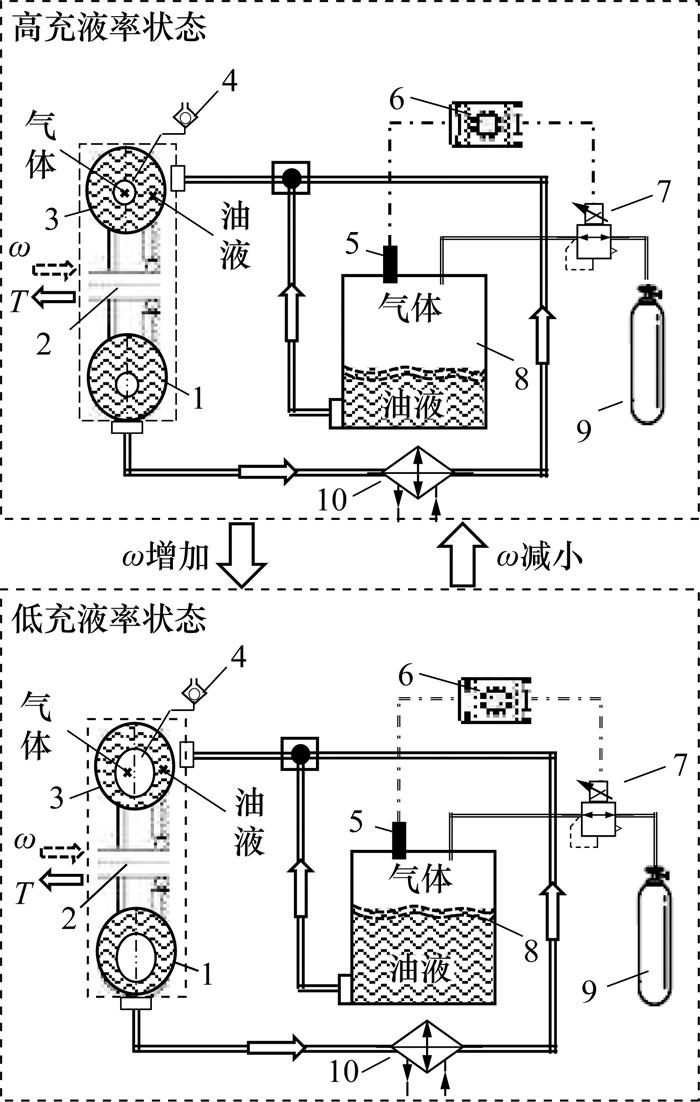
液力缓速器的工作腔和充放油控制系统是一个紧密联系并互相作用的整体。充放油控制系统根据指令将储油腔上部气体的压力控制为目标气压pc,推动储油腔中的油液进入工作腔中;在工作腔中,与输入轴相连的转子推动油液在定转子之间高速循环流动,利用油液的阻尼效应将转子的动能转换为油液的内能,从而实现T的输出;油液在工作腔中经过一定的循环流动后从出油口流出经散热器后再返回工作腔。
当ω为0时,只要储油腔实际气压pct大于外界大气压力,就会推动储油腔中的油液进入工作腔,工作腔原有的空气通过浮子室排入大气,当工作腔全部被油液占满后,浮子室通过浮球隔断工作腔和外界大气的连通,此时工作腔为满充液状态。当ω增大,工作腔中循环圆中心压力下降至低于外界大气压后,浮子室打开连通外界大气,外界大气可以重新进入工作腔中部,工作腔充液率q逐渐下降。此过程中,工作腔中减少的油液被迫压回储油腔,储油腔上部空气的体积被压缩,如果充放油控制系统不进行额外动作,pct将升高。当ω减小,油液从储油腔重新流入工作腔,q将逐渐增大直至工作腔为满充液率状态;此过程中,储油腔中油液减少,其上部气体的体积增大,如果充放油控制系统不进行额外动作,pct将降低。
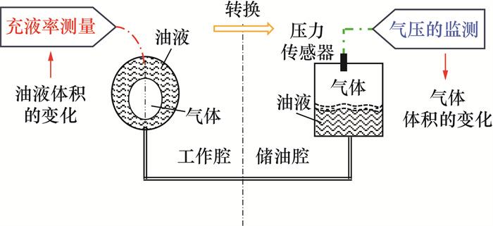
综上,忽略油液的可压缩性,q的增和减分别对应着充放油系统中储油腔中气体体积的增和减,如果充放油控制系统不进行额外动作,pct将随着q相应波动变化。利用这一特性,可将传统的q测量时对工作腔中油液体积的测量,转换为通过压力传感器对pct的监测,并基于理想气体方程将pct波动转化为气体的体积变化,从而间接地实现对q的测量,如图 2所示。
2 液力缓速器储油腔气压控制算法
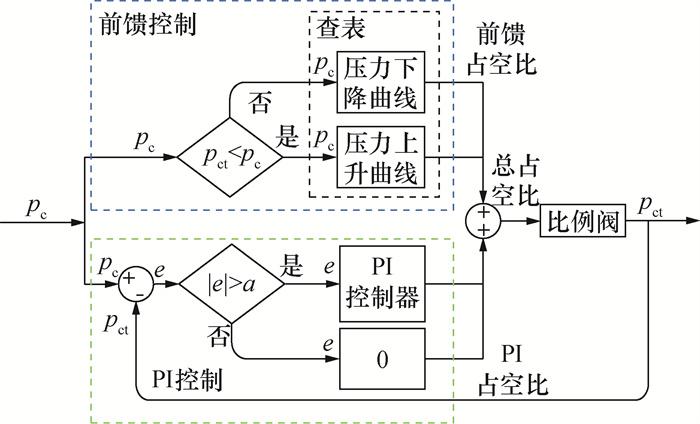
PI控制中,首先根据pc与pct的差值e的绝对值进行选择判断,当|e|大于a时,通过PI控制器进行计算输出PI占空比;当|e|小于或等于a时,PI控制器输出为0。在试验测试中发现,当a为10 kPa时能较好地实现pct的快速响应和较小的波动,因此本文中将a取为10 kPa。
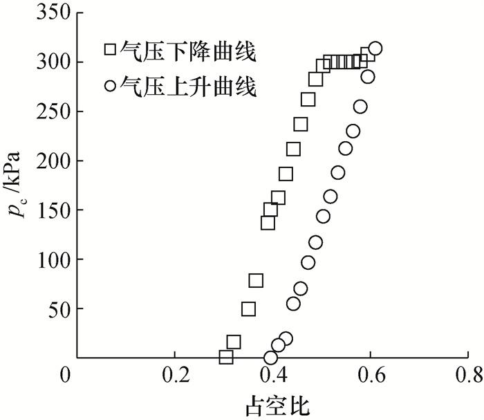
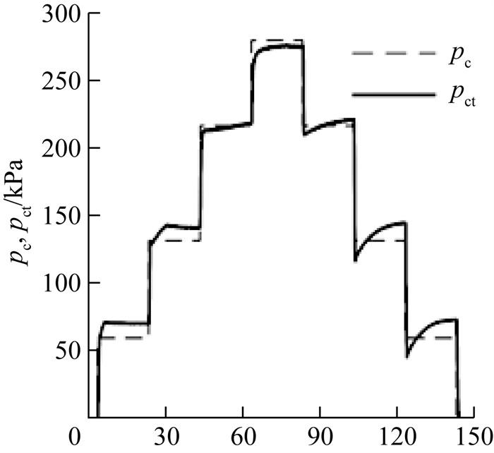
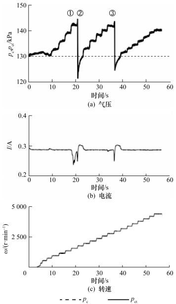
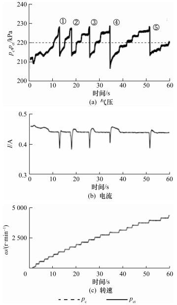
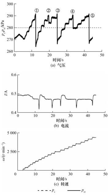
液力缓速器通常设置有4个固定挡位输出。图 5为60、130、220和280 kPa这4种挡位pc时液力缓速器静态闭环测试的pct,各挡位pc对应的pct最大误差约在10 kPa,各挡位之间切换响应时间在0.5 s左右(pct达到pc的80%)。此外,pct能快速达到稳定状态,超调振荡少。
3 充液率测量方法的建立
通过分析q变化对pct的影响可知,q的变化会造成储油腔中气体体积的变化,而充放油控制系统为维持pct不变,需要控制比例阀的阀芯进行对应动作,以维持pct在pc附近。结合所设计的液力缓速器储油腔气压的前馈PI控制策略,pct和q将随ω变化而改变,其变化过程如图 6所示。
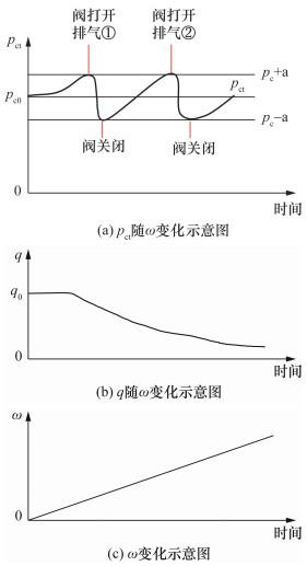
根据图 6,当ω=0时,pc0为初始气压;由液力缓速器结构特点,可知当ω=0时,在大于大气压力的pc0作用下,液力缓速器工作腔中将充满油液,初始充液率q0=1。随着ω升高超过一定的临界转速后,q开始减少,减少的油液被迫回流到储油腔中,忽略油液的压缩性,工作腔中减少的油液的体积等于储油腔中气体被压缩的体积,储油腔中气体被压缩后pct增加。
当压力传感器监测到pct超过(pc+a) 后,液力缓速器控制器发出信号控制比例阀进行排气动作;当压力传感器监测到pct小于(pc-a) 时,比例阀排气动作停止。然而随着ω进一步升高,q又继续减小,油液继续回流到储油腔,造成pct增大超过(pc+a) 后,液力缓速器又将重复进行一次短时排气动作,以此实现将pct控制在pc附近。
基于液力缓速器上述特性和储油腔气压的前馈PI控制策略,设计了如下的q测量方法:
首先根据液力缓速器的3-D模型测量液力缓速器内部空腔总容积VT和工作腔的空腔容积VW;测量液力缓速器中加入油液的总体积VO。
图 6中,从ω=0到第1次排气动作之前的第一阶段,储油腔内部空气总质量不变,根据理想气体方程可知
又因为在pct=pc0时q0=1,第1阶段工作腔充液率的表达式为
在第1次排气动作结束时,pct=pc-a,此时液力缓速器工作腔充液率为
同样,第1次排气动作结束后到第2次排气之前,储油腔内部空气总质量不变,因此第2阶段工作腔充液率的表达式为
第2次排气动作结束时pct=pc-a,此时液力缓速器工作腔充液率为
以此类推可得到第n阶段时充液率为
第n阶段结束时的充液率为
4 实验验证与分析
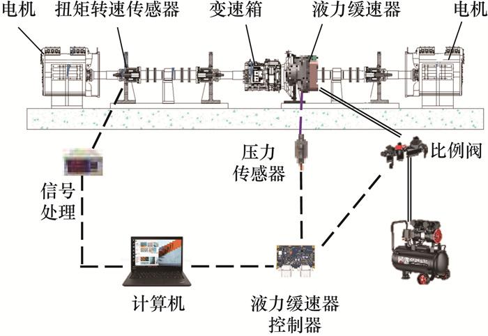
为了验证所建立的q测量方法的有效性,开展了液力缓速器样机的台架实验。图 7为液力缓速器测试台架系统,包括4台160 kW的电机、1台机械变速箱、1套转速扭矩采集系统、1台液力缓速器、1台空气压缩机和1台计算机。液力缓速器的热交换器的水道与一套功率大于400 kW的散热系统相连,散热系统包括1套车用风冷散热器和室外的2 t冷却水塔。
首先对试验选用的液力缓速器(见图 8)进行测量,得到VT=7.8 L、VW=1 L和VO=6.6 L。

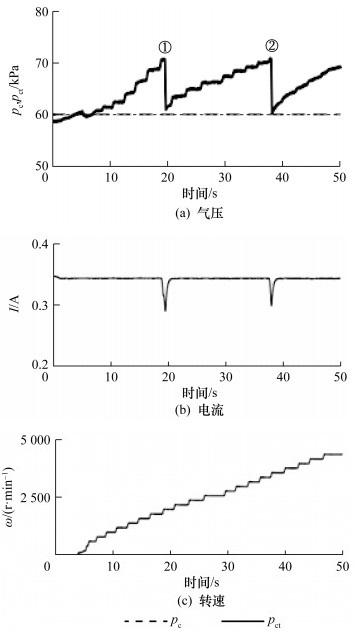
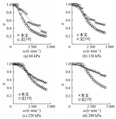
以=220 kPa时的pct变化曲线为例,运用提出的q测量方法进行计算。由图 11可以看出,整个过程中进行了5次排气动作,计算q时忽略5次实际排气过程的不一致性,均认为排气时pct从(pc+a) 下降至(pc-a),即每次排气时pct均从230 kPa下降至210 kPa。因此将整个过程划分为6个阶段,根据式(1)—(7)计算q。
阶段1的工作腔充液率为
由q0=1,可以计算得到qe=0.89。
以此类推,可得到阶段2到6各个阶段q的计算表达式和每次排气结束时的工作腔充液率:q2e=0.80,q3e=0.71,q4e=0.63,q5e=0.56。
pc=60、130和280 kPa三种情况下工作腔充液率可类似计算得到。

5 结论
本文提出了一种基于储油腔气压波动的液力缓速器工作腔充液率测量方法。利用液力缓速器储油腔气压随工作腔充液率变化而变化的这一特性,通过监测储油腔气压波动,无须额外增加流量传感器,基于储油腔目标气压、实际气压、目标气压允许的偏差值和液力缓速器关键容积设计参数,实现了液力缓速器工作腔充液率的测量。通过台架实验及与已有文献中方法的计算结果进行对比,验证了所提方法的有效性。本文方法解决了液力缓速器工作腔充液率的测量难题,可以为液力缓速器的设计优化提供关键核心参数支撑。
