Public Safety

Casing damage mechanism and failure segments determination of in situ combustion for heavy oil

  • Tianqi LIU 1, 2, 3, 4 ,
  • Shengnan WU , 1, 2, 3, 4, * ,
  • Laibin ZHANG 1, 2, 3, 4
Expand
  • 1. Hainan Institute of China University of Petroleum (Beijing), Sanya 572000, China
  • 2. College of Safety and Ocean Engineering, China University of Petroleum(Beijing), Beijing 102249, China
  • 3. Key Laboratory of Oil and Gas Production Safety and Emergency Technology, Ministry of Emergency Management, Beijing 102249, China
  • 4. Key Laboratory of Oil and Gas Production Equipment Quality Inspection and Health Diagnosis, State Administration for Market Regulation, Beijing 102249, China

Received date: 2025-02-02

  Online published: 2025-05-24

Copyright

All rights reserved. Unauthorized reproduction is prohibited.

Abstract

Objective: To thoroughly investigate the impact of high temperatures at the bottom of in-situ combustion wells on casing integrity, a finite element model (FEM) was developed to simulate the casing-cement sheath-formation system. The model was constructed based on the principles of heat transfer and material mechanics, enabling an in-depth analysis of the temperature distribution and equivalent stress distribution under combustion temperatures ranging from 500 ℃ to 650 ℃. This approach aimed to elucidate the thermal and mechanical behaviors of casing materials under extreme high bottomhole temperature conditions, thereby providing a reliable basis for casing risk assessment and design optimization. Methods: High-temperature tensile tests were performed on casing materials specifically designed for in-situ combustion wells. The tests assessed the mechanical properties of these materials, including yield strength and tensile strength, under elevated temperatures typically encountered in in-situ combustion operations. Allowable stress for different temperature ranges was determined using the safety factor method, which is widely used in engineering field to ensure the reliability of the casing structure. Additionally, a microscopic analysis of tensile fracture surfaces at various temperatures was conducted using scanning electron microscopy to investigate the temperature-induced casing failure mechanisms. Results: The results reveal significant changes in the fracture morphology of casing materials, highlighting a progressive degradation in the material properties as temperature increases. The Von Mises yield criterion is used as the failure assessment standard, allowing for a detailed comparison between equivalent stresses obtained from numerical simulations and experimental allowable stresses. This comparison identifies casing segments at a high risk of deformation and failure. Numerical simulations demonstrate that the casing within oil-bearing formations experiences substantial thermal expansion. Meanwhile, due to axial constraints at the top and bottom of a wellbore, the casing undergoes significant axial compression, resulting in compressive deformation. Furthermore, in ordinary rock formations, the casing expands freely but is subjected to formation stresses, leading to pronounced necking deformation. Experimental results show that once the temperature exceeds 500 ℃, the yield strength and tensile strength of casing materials decrease dramatically. The tensile fracture surfaces exhibit typical ductile fracture characteristics, accompanied by severe oxidation, confirming the adverse effects of high-temperature exposure on the mechanical performance and structural integrity of the casing. This mechanical performance degradation poses a considerable risk of failure, especially in high-temperature zones near the ignition segment. Conclusions: This study further reveals that the equivalent stress distribution within the casing is positively correlated with the temperature field. High bottomhole temperatures significantly expand the risk zones for casing damage, though the failure locations remain confined to the casing segment near the igniter. The primary failure mechanism is identified as compressive deformation caused by thermal stress, with oil-bearing formation segments being particularly vulnerable to failure due to restricted casing expansion caused by surrounding constraints. These findings provide valuable insights into the failure mechanisms of the casing under high-temperature conditions and offer practical guidance for improving the casing design and reliability in in-situ combustion for heavy oil. By integrating numerical simulations with experimental tests, a more comprehensive understanding of the casing behavior under extreme thermal and mechanical conditions achieves. This approach not only enhances risk assessment strategies but also supports the development of more robust casing solutions capable of withstanding harsh environments encountered in in-situ combustion wells. Ultimately, this research contributes to the sustainable development and improves safety of heavy-oil extraction projects, reducing operational risks and ensuring long-term profitability.

Cite this article

Tianqi LIU , Shengnan WU , Laibin ZHANG . Casing damage mechanism and failure segments determination of in situ combustion for heavy oil[J]. Journal of Tsinghua University(Science and Technology), 2025 , 65(6) : 1112 -1119 . DOI: 10.16511/j.cnki.qhdxxb.2025.22.027

随着常规油藏开采效益逐渐下滑,非常规采油技术在高黏度稠油开采中发挥着至关重要的作用。其中,火驱技术作为蒸汽吞吐与蒸汽驱的有效接替工艺,以更高的采收率和更广泛的适用油藏条件,成为稠油开采技术的重要发展方向。然而,火驱技术实施复杂、工艺要求高。当前国内外广泛采用的干式正向燃烧法的工作原理可概括如下[1-4]:将空气注入井筒并电加热,热空气渗透至储油岩层,直接加热并引发原油氧化放热反应,提升岩层温度,促使轻烃组分蒸馏分离并自燃;持续注入氧化剂促使井下形成径向燃烧前缘,前方原油经蒸馏裂解后,砂砾表面沉积的焦炭作为燃料维持燃烧;与此同时,高温条件下产生的水汽携带热量向外扩散,与火驱、烟气驱及热水驱多重作用并相互协同,从而显著降低原油黏度,促使原油向生产井流动并实现高效采收。相比于传统蒸汽驱工艺,火驱技术不仅能够提高稠油采收率,还在深部油藏及高黏度原油储层中展现出良好的适应性与经济性,具有广阔的应用前景。
在稠油火驱开采中,注入井的井底温度从点火初期200 ℃迅速升至稳定燃烧期650 ℃,然后随燃烧前缘推进而缓慢下降,恢复至原始地层温度[5]。辽河油田Du-66区块井筒完整性调查显示,截至2015年底,在92井群生产平台,43口井中有28口井从蒸汽驱转为火驱后出现不同程度的套管损伤或变形[6]。在火驱技术中,套管面临比传统蒸汽驱(450 ℃以内)更为严苛的高温工况,峰值温度可达500~650 ℃,高温导致材料性能显著下降,进而造成套管热应力损伤。
国内外学者对热采套管损伤问题开展了大量研究:通过开展材料性能试验[7-8],探究了高温对套管材料屈服强度、弹性模量及热膨胀系数的影响[9-11],并通过观察材料破坏形貌[12],分析了套管失效机理,建立了温度影响下的套管强度校核方法;通过套管-水泥环-地层热力耦合有限元模型[13-14],探讨了注气条件下井筒温度的分布情况,计算了热采井中管柱所受三轴热应力的分布[15-16],深入研究了注汽循环过程中水泥环缺陷[17]、地层非均质性等导致套管承受非均匀载荷并发生失效的问题;通过评估蒸汽循环过程套管产生的应变及塑性变形行为,探究了套管损伤机理,致力于排查关键风险因素[18],以提出基于应变变化的热采套管设计方法;通过基于套管力学行为和现场实践数据的工程框架,评估了热采井用套管在承受温度和压力载荷时的结构完整性[19],并利用相关模拟装置研究了热采井套管、地层附近的温度分布和热应力分布[20-22],使得套管失效预测成为可能。
迄今为止,国内外学者围绕套管温压耦合分析、管材强度校核及套管材料高温力学性能进行了大量研究。然而,现有研究[7-22]大多聚焦于注汽热采井的温压耦合模拟,研究重点主要集中在环空注入高温流体至地层过程中的径向传热效应,对火驱工况下井底套管面临的复杂热环境及高温变形机制关注较少。在稠油火驱过程中,井底套管不仅受到环空热流体的热传导作用,还受到燃烧储层的强烈热辐射和对流传热影响,损伤机理较为复杂。然而,目前鲜有研究针对如此高温环境下套管变形失效的临界条件进行系统的力学性能试验与数值模拟。
本文通过建立套管-水泥环-地层三维有限元模型,全面考虑井筒各组件间的热传导效应、环空与周围组件的热对流效应及燃烧储层的热辐射效应,模拟火驱井井筒内的温度场分布。在此基础上,添加边界约束条件,模拟套管在热效应和机械载荷共同作用下的等效应力分布,从而获得更接近现场实际工况的应力响应数据。同时,开展套管材料试样高温拉伸试验,获取不同高温条件下的屈服强度和抗拉强度等力学性能参数数据,并将数值模拟得到的套管等效应力与高温试验结果进行对比。依据Von Mises屈服准则,识别可能存在失效风险的套管段,揭示高温条件下套管的变形失效机制。本研究结果不仅可以为火驱井套管完整性分析提供关键数据支持,还可以为蒸汽驱向火驱转换过程中套管材料的适用性及风险评估提供科学依据,对于火驱井筒结构优化设计及材料选择具有重要意义。

1 方法过程

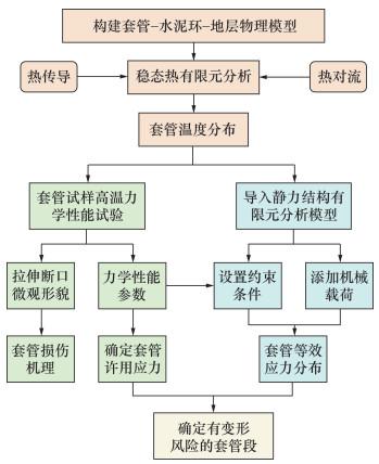
构建了稠油蒸汽驱转火驱井中套管在高温高压环境中失效判断及机理分析流程图,如图 1所示。首先,建立套管-水泥环-地层装配体模型,以传热学原理和材料力学第4强度理论为基础,将装配体导入稳态热有限元分析模型,得到套管轴向温度分布。以50 ℃为温度梯度,开展套管试样在对应温度下的拉伸试验,得出屈服强度、抗拉强度等力学性能参数数据,确定套管材料的安全极限;选取两组试样断口进行电镜观测,分析断裂微观形貌,得到断裂机理。同时,根据目标油田实际井况,获取机械载荷,导入静力结构有限元分析模型,叠加稳态热模块求得的温度载荷,得出套管各单元的等效应力。最后根据Von Mises屈服准则,判断套管各单元承受的等效应力是否在安全极限内,从而确定有变形失效风险的套管段,完成失效判断。
图 1 套管失效判断及机理分析流程图

1.1 套管试样高温拉伸试验

拉伸试验根据GB/T 228.2—2015 《金属材料拉伸试验第2部分:高温试验方法》选取板材拉伸试样,使用E45.105型微机控制电子万能试验机进行试样拉伸,具体步骤如下:
1) 试验前,对试样尺寸进行检查、测量并按照要求标记标距、清洗试样。
2) 在试验加载链装配完成后、试样两端被夹持之前,设定力测量系统的零点。
3) 安装热电偶。将热电偶绑接在试样工作端上,试样两端螺纹分别拧入试验机的上、下夹具。
4) 安装引伸计。将标定好的引伸计夹到试样工作部分。
5) 分级加热升温,到达500 ℃后保温30 min后开始试验。
6) 按“开始”按钮进行试验。当试样变形超过屈服强度测量变形0.2%的值后,需要移除引伸计,防止引伸计损坏。继续试验,直到试样拉断,待炉温降至室温后卸下试样,测量并记录试样断口标距、断口处的直径。
7) 试验结束后,保存试验数据,退出试验软件。
8) 重复步骤1)至7),继续装载新试样并分别升温到550、600和650 ℃,每个温度的试验重复3次。拉伸试样断口直接切片制样,通过超声波清洗后,进行Sigma 300电子扫描显微镜观察,分别拍摄宏观断口形貌和断口源区特征。

1.2 套管等效应力数值模拟

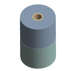
以蓬莱油田某井为例,该井油藏条件良好。由于燃烧的储油岩层与普通岩层交界过渡的井段温差较大,产生的热应力使套管在此段有轴向变形至失效的风险,故主要研究深入储油岩层5 m至普通岩层5 m的井段,共10 m。本文建立的模型为理想化模型,故提出如下假设:套管、水泥环、地面胶结良好,地层分为上部普通岩层和下部储油岩层;热膨胀系数、比热容、导热系数随温度变化不大,视为恒定;井下燃烧稳定,且燃烧前缘推进缓慢,故假定是均匀加热、稳态传热。首先,构建套管-水泥环-地层装配体物理模型,如图 2所示。
图 2 套管-水泥环-地层装配体模型
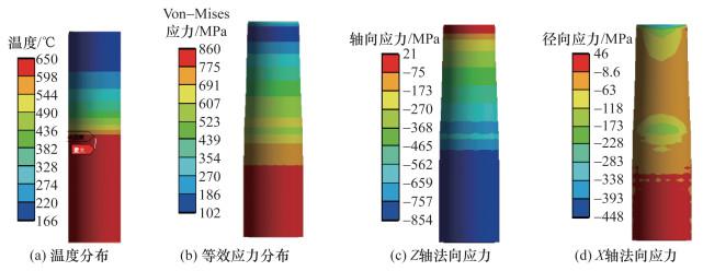
将装配体导入热力耦合有限元分析模型,建模参数如表 1所示。网格划分以六面体为主导。设置温度载荷,模拟套管附近储油岩层燃烧到500、550、600、650 ℃ 4种极端工况。设置压力载荷,上覆岩层压力设为20 MPa,水平地层压力设为10 MPa,内压设为10 MPa。设置边界条件:套管底端压缩支撑,套管顶端XY方向自由度为0,Z方向自由。检查网格质量并逐步细化网格。对比不同网格尺寸下套管最大等效应力的变化趋势,确保将网格尺寸对模拟结果的影响降到最低,以提高模拟结果的准确性。
表 1 套管-水泥环-地层有限元模型建模参数
组件 弹性模量/GPa 密度/(kg·m-3) Poisson比 热膨胀系数/(10-6-1) 比热容/(J·kg-1·K-1) 导热系数/(W·m-1·K-1)
套管 207.0 7 800 0.3 13.7 506 29.0
水泥环 4.8 1 900 0.2 7.9 618 1.6
地层 4.8 2 750 0.2 11.3 903 2.4

2 结果和讨论

2.1 套管高温力学性能及损伤机理分析

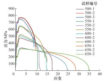
火驱井套管试样在不同温度下的拉伸应力-应变曲线如图 3所示。试样编号中,例如“500-1”,表示500 ℃下的第1次试验。在500 ℃条件下,3组试样应力-应变曲线基本一致,屈服强度、抗拉强度等比较稳定。在550、600、650 ℃下,弹性阶段和屈服阶段曲线走向一致,但过了强化阶段,3组试样曲线开始无序,表现为断后伸长率不一致。500和550 ℃时,弹性阶段结束后,存在明显的屈服阶段,曲线呈锯齿状,应变增加而应力不变,材料失去抵抗变形的能力;进入强化阶段,材料恢复抵抗变形的能力,随应变增加应力快速上升;在到达抗拉强度后,进入颈缩阶段,应力快速下降,直至断裂。在600和650 ℃时,屈服阶段锯齿状不明显,很快进入颈缩阶段,并且断裂时的应变较500和550 ℃时明显增大。
图 3 不同温度下TP110H钢试样拉伸曲线
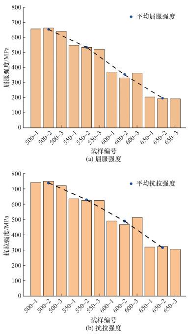
不同温度下,套管材料的拉伸性能如图 4所示,其屈服强度、抗拉强度均随温度升高而显著下降。
图 4 不同温度下TP110H钢力学性能
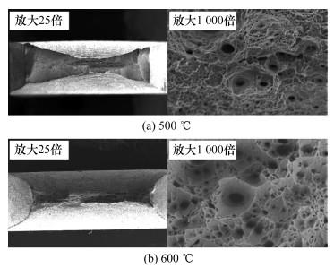
为了进一步确认高温拉伸断裂机理,拍摄了试样在500和600 ℃下的断口微观形貌,如图 5所示。由图 5a可以看出,在500 ℃时,断口较为平坦,表面呈灰黑色,试样产生了严重的颈缩变形,断口长3.7 mm、宽488.5 μm;断裂起始于长方形试样的中心,纤维源区呈现韧性断裂特征,存在大量细小的韧窝,较大韧窝直径平均为19 μm;放射区由不在同一平面的多个斜面组成,可见少量较深的二次开裂,长度在14 μm左右;断面上有浅而小的韧窝,剪切唇占比很小,呈现剪切韧窝形貌。由图 5b可以看出,在600 ℃时,断口宏观形貌和纤维源区的特征未发生明显改变,皆为韧性断裂特征,断口长3.1 mm、宽288.8 μm,颈缩严重,观察到尺寸较大的韧窝,平均直径为22 μm,二次裂纹长度在24 μm左右。韧窝尺寸随温度升高而增大,说明TP110H钢有较好的延展性,但氧化比较严重。
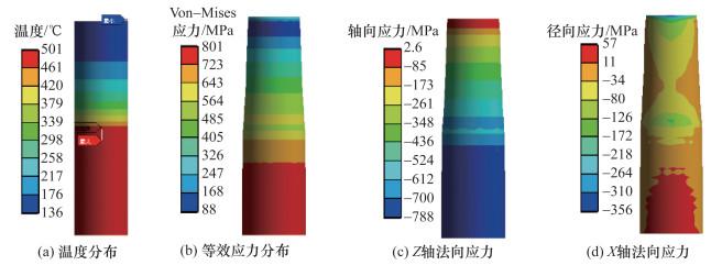
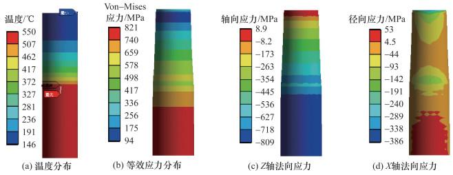
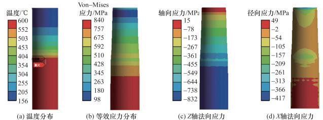
图 5 拉伸断口宏观及微观形貌

2.2 火驱套管温度及应力分布

500、550、600、650 ℃ 4种燃烧工况下,套管温度及等效应力分布如图 69所示。可以看出,套管底部的温度接近储油岩层燃烧温度;由于地层无限远且散热良好,加上环空的对流换热作用,由储油岩层过渡到普通岩层的套管段温度缓慢下降;深入储油岩层的套管段受热膨胀发生了明显的径向扩张变形,受顶端约束影响,轴向发生了明显的压缩变形;处于普通岩层的套管段受地层载荷影响,发生了颈缩变形;套管的等效应力分布与温度分布呈正相关,而等效应力的大小主要是Z轴法向应力贡献的。
图 6 井底500 ℃燃烧温度下套管温度及应力分布
图 7 井底550 ℃燃烧温度下套管温度及应力分布
图 8 井底600 ℃燃烧温度下套管温度及应力分布
图 9 井底650 ℃燃烧温度下套管温度及应力分布

2.3 火驱套管失效区间确定

以普通岩层和储油岩层的交界处作为0点,向上延伸深入普通岩层的套管段为正,向下延伸深入储油岩层的套管段为负。井底4种燃烧工况下,套管轴向的等效应力分布如图 10所示。以对应温度下套管许用应力为衡量标准,在图 10中用蓝色点划线示意了风险临界值。可以发现,深入储油岩层的套管,其等效应力远远超过了套管许用应力,TP110H钢难以抵抗500 ℃以上的高温;深入普通岩层的套管,其等效应力随热量向地层的扩散而逐渐降低,但与储油岩层的交界处,由于温差较大,仍然存在一个区间面临失效的风险。
图 10 不同燃烧工况下套管轴向等效应力分布
深入地层的套管段面临失效风险的精确区间如表 2所示。表 2中列出了试验所得的屈服及抗拉强度,并根据安全系数法计算出各个温度对应的许用应力。然后,根据图11找出各个燃烧阶段中的风险临界点,此点对应的Z轴坐标到0点的区间即为有失效风险的井段。表 2中数据表明,对于TP110H钢套管,井下500 ℃高温燃烧时,有4.5 m的套管段面临失效风险;550 ℃高温燃烧时,大约6 m的套管段面临失效风险;尽管实际操作中套管不会直接承受600 ℃以上的高温,然而因火线管控不当导致火窜时,大约10 m的套管段会面临失效风险。
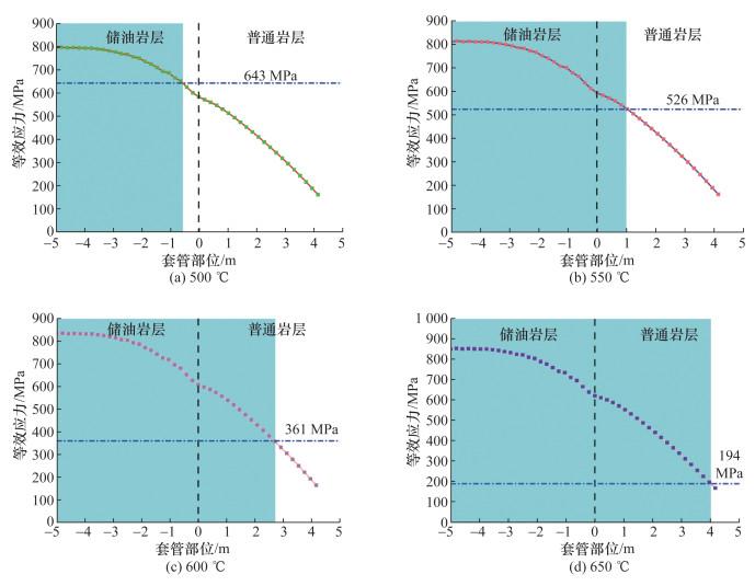
表 2 高温拉伸试验与有限元模拟结果比对
温度/℃ 屈服强度/MPa 抗拉强度/MPa 许用应力/MPa 临界等效应力/MPa 有失效风险的套管段/m
500 656 735 643 623 -5.0~-0.5
550 537 626 526 514 -5.0~1.0
600 368 488 361 336 -5.0~2.7
650 198 316 194 190 -5.0~4.0

3 结论

在前人对蒸汽驱井温度场和热应力模拟研究的基础上,本研究进一步明确了火驱井套管的许用应力值,并识别了具体存在失效风险的套管部位,从理论上明确了稠油火驱井套管的损伤临界条件及损伤机理,为现场维护井筒完整性提供了重要的参考依据和损伤防控思路。主要结论如下:
1) 随着温度的升高,套管材料TP110H钢的屈服强度和抗拉强度显著降低。通过拉伸断口形貌分析发现,纤维源区呈现出典型的韧性断裂特征,断口上分布着大量细小的韧窝和少量二次裂纹,且韧窝尺寸随温度的升高逐渐增大。这表明TP110H钢在高温环境下仍具备较好的延展性,但断口区域氧化现象严重,可能对套管材料的长期服役性能产生不利影响。
2) 数值模拟和试验结果表明,与燃烧的含油储层直接接触的套管段因受高温热应力作用,存在较高的失效风险。然而,该段套管的损坏并不会显著影响注气和井下燃烧过程,因此对整体采油作业影响较小。相比之下,位于普通岩层中的套管段在地应力和热应力的共同作用下,易发生颈缩变形并有局部失效风险。这种变形可能对注气工艺产生不利影响,甚至导致注气效率下降,需引起特别关注并采取针对性防控措施。
3) 在实施火驱工艺的过程中,针对套管失效风险,应控制点火温度在500 ℃以下,合理分段点火,降低热应力峰值;应在高温储层与套管接触部位增加隔热层,选用高温抗氧化合金材料,提升套管耐高温性能;应采用地层压力管理和井眼结构优化技术,减少地层应力引起的套管颈缩失效;应构建实时监测与井筒健康管理系统,实现风险预警与状态评估。未来,通过多学科交叉技术与智能化管理,稠油火驱井筒完整性将进一步提升,为稠油开采提供高效、可持续的技术支撑。
1
LIU D , TANG J S , ZHENG R N , et al. Determination of the propagation state of the combustion zone during in-situ combustion by dimensionless numbers[J]. Fuel, 2021, 284, 118972.

DOI

2
ZHAO S , GAO H M , PU W F , et al. Isothermal oxidation behavior of heavy crude oil and its low-temperature oxidized oils: Implications for in-situ upgrading of heavy oil[J]. Fuel, 2022, 313, 122704.

DOI

3
MANRIQUE E J , TRUJILLO M L , LIZCANO J C , et al. Comprehensive fluid compositional analysis program to support the interpretation of Chichimene field in-situ combustion pilot[J]. SPE Reservoir Evaluation & Engineering, 2023, 26 (2): 290- 304.

4
MINAKOV A V , MESHKOVA V D , GUZEY D V , et al. Recent advances in the study of in situ combustion for enhanced oil recovery[J]. Energies, 2023, 16 (11): 4266.

DOI

5
YUAN S B , REN Z H , YANG F X , et al. Numerical simulation on characteristics and mechanisms of steam-assisted in-situ combustion in extra-heavy oil reservoirs[J]. Energy, 2024, 312, 133619.

DOI

6
YANG S Y , HAN L H , FENG C , et al. Mechanical performance of casing in in-situ combustion thermal recovery[J]. Journal of Petroleum Science and Engineering, 2018, 168, 32- 38.

DOI

7
GRUBEN G , DILLINGH B , KALDAL G S , et al. Thermo-mechanical tensile testing of geothermal casing materials[J]. Geothermics, 2021, 89, 101944.

DOI

8
FAN Z J , ZHONG X K , YAO J X , et al. Analysis on the fitness of heat-resistant steel as casing material in corrosive environment at high temperature[J]. Engineering Failure Analysis, 2023, 143, 106878.

DOI

9
蒋东雷, 余意, 王恒, 等. 海上油气田油套管用材110Cr13S适用性研究[J]. 材料保护, 2023, 56 (7): 105-109, 193.

JIANG D L , YU Y , WANG H , et al. Study on applicability of oil casing material 110Cr13S for offshore oil and gas fields[J]. Materials Protection, 2023, 56 (7): 105-109, 193.

10
REN S Q , ZHAO J , KANG Z Q , et al. Suitability analysis of the deformation behavior of metal corrugated casing in high-temperature wellbore[J]. Energies, 2023, 16 (16): 5966.

DOI

11
REN X Y , WU J J , WANG C K , et al. Research on property and burning behavior of flammable casing for underground coal gasification[J]. Heliyon, 2023, 9 (12): e22232.

DOI

12
王娇娇, 赵林林, 高云哲, 等. 回火温度对深井石油套管用钢组织性能的影响[J]. 金属热处理, 2024, 49 (3): 112- 115.

WANG J J , ZHAO L L , GAO Y Z , et al. Effect of tempering temperature on microstructure and properties of an oil casing steel used for deep wells[J]. Heat Treatment of Metals, 2024, 49 (3): 112- 115.

13
LIAN W , LI J , XU D R , et al. Sealing failure mechanism and control method for cement sheath in HPHT gas wells[J]. Energy Reports, 2023, 9, 3593- 3603.

DOI

14
HOU D , ZHANG Z , GENG Y N , et al. Study on channeling-leakage pressure of casing-cement sheath-stratum assembly in thermal recovery wells[J]. Fuel, 2024, 356, 129592.

DOI

15
HUO J , HAN C , SONG L , et al. Safety and reliability evaluation of casing strength under annulus pressure in ultra-deep wells during oil and gas development[J]. Fresenius Environmental Bulletin, 2021, 30 (1): 631- 637.

16
李宗锟. 稠油热采井套管损坏机理及套管挂片技术实验[J]. 特种油气藏, 2021, 28 (2): 171- 174.

DOI

LI Z K . Damage mechanism of casing for thermal recovery of heavy oil well and casing coupon technology experiment[J]. Special Oil & Gas Reservoirs, 2021, 28 (2): 171- 174.

DOI

17
WU Y , ZHOU J L , YANG J , et al. A study on the integrity evaluation of cement sheaths for deep wells in deep water[J]. Energies, 2022, 15 (16): 5814.

DOI

18
XU J , DENG J G , CHEN Y , et al. Analysis of casing instability and factors influencing it in thermal production oil wells[J]. Chemistry and Technology of Fuels and Oils, 2021, 57 (5): 804- 812.

DOI

19
ZHAO X Y , LUO H , YANG M , et al. Novel method for optimization cement slurry based on the wellbore integrity model in high-temperature and high-pressure conditions[J]. ACS Omega, 2023, 8 (48): 45668- 45677.

DOI

20
JIANG H L , ZHANG T , XI Y , et al. Transient temperature and pressure coupling model of cementing injection stage in ultra deep wells considering segmental rheological model, casing eccentricity and U-tube effect[J]. Geoenergy Science and Engineering, 2024, 243, 213384.

DOI

21
梁疆岭, 杨洪, 苏宏益, 等. 稠油热采井射孔孔眼应力分析及影响因素[J]. 特种油气藏, 2024, 31 (1): 152- 158.

LIANG J L , YANG H , SU H Y , et al. Stress analysis and influencing factors of perforation in heavy-oil thermal recovery wells[J]. Special Oil & Gas Reservoirs, 2024, 31 (1): 152- 158.

22
WANG S W , CHEN X , HE M , et al. Coupled modeling circulating multi-layer wellbore temperature and stress field during deepwater high-temperature and high-pressure gas well testing[J]. Thermal Science and Engineering Progress, 2024, 47, 102356.

DOI

Outlines

/