Mechanical Engineering

Finite element simulation and optimization design of parameters for magnetic control actuator in spinal curvature growth rod system

  • Yumei LI 1, 2 ,
  • Ding LU 1, 2, 3 ,
  • Yunzhi CHEN 3, 4 ,
  • Yanjie XU 3, 4 ,
  • Tairan PENG 3, 4 ,
  • Gang FU 5 ,
  • Zhenguo NIE , 3, 4, *
Expand
  • 1. Beijing Key Laboratory of High Dynamic Navigation Technology, Beijing Information Science & Technology University, Beijing 100092, China
  • 2. Key Laboratory of Modern Measurement & Control Technology, Ministry of Education, Beijing Information Science & Technology University, Beijing 100092, China
  • 3. Department of Mechanical Engineering, Tsinghua University, Beijing 100084, China
  • 4. State Key Laboratory of Tribology in Advanced Equipment, Tsinghua University, Beijing 100084, China
  • 5. Beijing Jishuitan Hospital, Beijing 102208, China

Received date: 2025-01-08

  Online published: 2025-11-07

Copyright

All rights reserved. Unauthorized reproduction is prohibited.

Abstract

Objective: The magnetic expansion control (MAGEC) system, developed by NuVasive, has demonstrated positive surgical outcomes in treating early-onset scoliosis. However, clinical studies have indicated that the MAGEC system is challenged by insufficient tensile force, which can lead to failed elongation surgeries. The maximum torque of the rotor inside the growth rod significantly affects the tensile force of the growth rod. The larger the maximum torque of the rotor, the greater the tensile force of the growth rod. Because of the different body weights of patients, the relative positioning of the rotor and driver in the clinical application of the MAGEC system is also different. Therefore, the distribution space in which the rotor can rotate continuously has a significant impact on clinical treatment. To solve the problem of insufficient tensile force, it is necessary to optimize the maximum torque of the rotor and to maximize the distribution space for continuous rotation of the rotor. Methods: This study employs ANSYS Maxwell to establish a finite element simulation model for a circular distributed drive permanent magnet rotor system. The analysis investigates the effects of the angle between the drive permanent magnet and the rotor, pole pairs, rotor outer diameter, and drive permanent magnet speed on the maximum torque of the rotor, and determines the continuous rotation domain of the optimized rotor. To verify the simulation results, a rotor torque measurement device was built and connected to a coupling through a motor. Furthermore, a growth rod extension experiment was conducted to test the magnetron-drive performance. Finally, a growth rod tensile-force testing platform was constructed to test the maximum tensile force of the growth rod. Results: The experimental results demonstrate that optimal performance was achieved when the angle between the driving permanent magnet and rotor was set to 120°, a single pole pairs configuration and an 8-mm outer diameter of the rotor. This combination produces the maximum torque of the rotor and the most extensive continuous rotation distribution space. However, the speed of the driving permanent magnet did not affect the maximum rotor torque. The maximum torque of the rotor before optimization was 32.847 N·mm; The maximum torque of the optimized rotor was 98.970 N·mm, which was 201% higher than that before optimization, and the distribution space for continuous rotation of the rotor was larger. The experiment demonstrated that the maximum torque values of the rotor before and after optimization were 30 and 90 N·mm, respectively, with relative errors of 8.7% and 9.06%, and that the permanent magnets could rotate stably. The maximum tensile force of the growth rod could reach 413 N, nearly twice the maximum tensile force of 208 N of the MAGEC system growth rod. Conclusions: When the angle between the driving permanent magnet and the rotor was set to 120°, the θ values that caused the maximum torque of the rotor to change from large to small were 120°, 140°, 100°, 160°, 80°, 180°, 60°, and 40°. The larger the number of pole pairs, the more rapidly the maximum rotor torque decreases. In addition, the larger the outer diameter of the rotor, the greater the maximum torque of the rotor. Finally, the rotational speed did not affect the maximum rotor torque.

Cite this article

Yumei LI , Ding LU , Yunzhi CHEN , Yanjie XU , Tairan PENG , Gang FU , Zhenguo NIE . Finite element simulation and optimization design of parameters for magnetic control actuator in spinal curvature growth rod system[J]. Journal of Tsinghua University(Science and Technology), 2025 , 65(11) : 2316 -2323 . DOI: 10.16511/j.cnki.qhdxxb.2025.21.025

早发性脊柱侧弯会影响儿童心肺发育和身心健康, 影响骨盆三维运动, 患者的生理曲度和骨盆形态会在脊柱侧弯生长过程中发生变化, 严重时可导致心肺衰竭。当脊柱侧弯严重并且持续恶化时, 通常采用生长棒进行手术干预[1-2]。由NuVasive公司研发的磁扩张控制(magnetic expansion control, MAGEC)系统在治疗早发性脊柱侧弯取得了较好的手术治疗效果, 该系统主要包括外部驱动器和生长棒, 外部驱动器内有一对同规格的驱动永磁体, 驱动永磁体通过产生旋转磁场带动生长棒内部转子转动从而产生转矩输入, 经扭矩增益及运动变换后使生长棒实现轴向延长或收缩, 且生长棒最大牵伸力可达到208 N[3-7]。但临床研究发现, MAGEC系统普遍存在牵伸力不足的问题[7], 牵伸力不足会导致延长手术失败, 无法有效治愈病症。为了解决此问题, 需要提高转子的最大扭矩并且使转子能够连续转动的分布空间尽可能大。转子最大扭矩对生长棒的牵伸力有很大的影响, 转子最大扭矩越大, 生长棒的牵伸力越大。由于患者体重不同, MAGEC系统在临床应用时转子和驱动器的相对位置也不一样, 因此转子可连续转动的分布空间对临床治疗有较大影响。
针对永磁电机转矩分析及优化, 很多学者采用不同方法进行了研究, Sun等[8]优化了永磁同步电机的结构、气隙长度和定子铁芯几何形状, 优化后的永磁同步电机转矩脉动减小了24%。Zhou等[9]提出了一种考虑电动汽车行驶工况的多目标优化方法, 通过多目标遗传算法对电动汽车永磁电机的转矩脉动、输出转矩进行优化。优化后的电机在重载、频繁启停爬坡工况下, 转矩脉动降低了33.5%, 输出转矩提高了7.84%; 在高速巡航下, 输出转矩提高了3.6%。Shi等[10]通过有限元分析, 研究了不同倾斜角下永磁同步电机的齿槽转矩和动态特性, 通过优化函数得到了最优倾斜角度。Bingi等[11]提出了一种基于神经网络的永磁同步电机转矩预测模型, 结果表明模型的预测值与实际值误差较小, 该方法在不增加传感器的情况下, 能对电机的转矩进行预测。Güemes等[12]分析了不同的20极三相永磁同步电机槽数对电机转矩的影响, 分析结果表明, 分数槽绕组电机具有较低的齿槽转矩和转矩脉动, 但平均转矩降低。王洪涛[13]在Ansoft Maxwell仿真环境下, 建立了内嵌式W形和U形结构永磁同步电机的二维和三维模型, 计算了2种永磁同步电机分别在空载和负载两种运行状态下的反电动势、定子电流、转速和电磁转矩。结果表明, 空载时W形比U形永磁同步电机的起动速度快、起动电流小、起动转矩平稳; 负载时W形比U形永磁同步电机的定子电流有效值略大, 但转速恢复的时间短, 电磁转矩波动小。Ebrahimi等[14]提出了一种新型的永磁电机结构, 通过推导该结构齿槽转矩的解析模型以及进行有限元分析, 确定了转子极弧系数的最佳值, 结果表明新结构在齿槽转矩、平均电磁转矩、转矩脉动、转矩密度和峰值转矩输出等方面都有明显改善。Yan等[15]将永磁电机磁极边缘效应转化为各极段产生的齿槽转矩的幅值和相位偏移, 以齿槽转矩为优化目标, 通过对优化问题的定量求解, 得到了各分段的最佳磁极长度参数, 结果表明优化后的齿槽转矩变小。于仲安等[16]以齿槽转矩和输出平均转矩为优化目标, 提出了一种新型非对称永磁同步电机结构并对其进行了优化设计, 优化后降低了电机的转矩波动, 同时验证了优化方法的有效性。周大伟等[17]借助Ansys Maxwell模块对高速永磁同步电机参数化建模, 运用遗传算法对电机进行全局多目标优化。结果表明, 电机转矩脉动从6.21%降低至2.96%; 电机齿槽转矩从0.341 N·m降低至0.052 N·m, 降低近85%。卢东斌等[18]提出了相同转速转矩下的多永磁同步电机系统效率模型, 并进行了仿真和试验验证; 结果表明, 平均分配永磁无刷轮毂电机转矩可使整车效率最优。张猛等[19]提出了一种基于区域电压矢量表的永磁同步电机直接转矩预测控制方法, 根据电机模型, 得到了在每个区域内电压矢量的预测控制角, 实现转矩和磁链的预测控制; 实验结果表明, 该方法的稳态转矩和磁链脉动比传统直接转矩控制的小, 同时还保持了传统直接转矩控制进行Bang-Bang控制鲁棒性好和转矩响应快的优点。上述方法为永磁电机转矩分析及优化提供了方向, 多位学者通过结构优化、有限元分析等方法, 有效提高了电机的输出转矩和效率。但这些优化方法大多只关注于提升电机的整体性能参数, 而对转子扭矩的优化较少。
转子存在可连续转动区域, 在该区域内转子能够随驱动永磁体同步转动。对于MAGEC系统这类由永磁体驱动转子的装置, 需要开展有针对性的研究, 以提升转子的最大扭矩和可连续转动的分布空间。本文利用Ansys-Electronics 2023R2的Maxwell模块建立圆周分布驱动永磁体-转子有限元动磁场仿真模型, 研究了驱动永磁体与转子间夹角、极对数、转子外径、驱动永磁体转速对转子最大扭矩的影响, 确定了转子能够连续转动的分布空间。同时, 为检验磁控驱动器的性能, 搭建了转子扭矩测量装置及生长棒实验装置, 对仿真结果进行了验证。

1 理论模型

1.1 磁控生长棒MAGEC系统简介
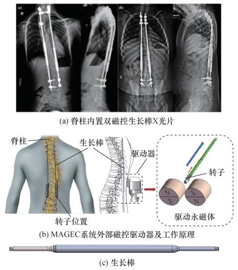
当脊柱侧弯严重并且持续恶化时, 通常需植入可生长的单、双侧生长棒进行手术干预。生长棒两端分别固定于脊柱上胸段和腰段, 利用撑开力可有效矫正脊柱畸形。相比单侧生长棒, 双侧生长棒具有稳定性好、治疗效果更加显著的优势, 图 1a为脊柱内置双磁控生长棒X光片[3]图 1b为MAGEC系统外部磁控驱动器及工作原理图。磁控驱动器内部核心元件由2个同规格的永磁体组成, 其绕各自中心轴顺时针同步旋转, 通过齿轮传动带动2个永磁体同步转动产生旋转磁场, 从而带动生长棒内部转子转动产生转矩输入, 经转矩增益实现生长棒轴向延长或收缩。图 1c为生长棒结构示意图。
图 1 磁控生长棒系统原理图

1.2 磁驱扭矩模型

MAGEC系统的驱动永磁体及转子均为圆柱形, 圆柱永磁体的磁力计算公式可以通过磁场强度和永磁体形状参数来进行推导, 而永磁体的磁化强度与磁场强度有关:
$\begin{equation*}J=(B-H) / \mu_{0} . \end{equation*}$
其中: J表示磁化强度, B表示磁感应强度, H表示磁场强度, μ0表示真空中的磁导率。
磁矩与永磁体的磁化强度和形状参数有关:
$\begin{equation*}M=\mathsf{π} r^{2} L J . \end{equation*}$
其中: M表示磁矩, r表示圆柱永磁体的半径, L表示圆柱永磁体的长度。
磁力由磁场强度和磁矩共同决定:
$\begin{equation*}F=\mu_{0} M q /\left(2 \mathsf{π} R^{3}\right) . \end{equation*}$
其中: F表示转子所受磁力, q表示外部永磁体的磁化强度, R表示转子与外部永磁体之间的中心距离。
圆柱转子扭矩的基本公式为
$\begin{equation*}T=k F /(2 \mathsf{π} ) . \end{equation*}$
其中: T是扭矩, k是扭矩系数。
由式(1)—(4)可知: 转子扭矩与其磁化强度、外部永磁体的磁化强度、转子半径和长度、转子与外部永磁体之间的中心距离有关。

1.3 控制方程

由于永磁体产生的外部磁场中没有电流的存在, 因此Maxwell模块在磁场仿真时选用“磁场, 无电流”模块, 控制方程为:
$\nabla \times H=0, $
$\nabla \cdot B=0, $
$B=\mu_{0}\left(H-H_{C}\right), $
$H=-\nabla V_{m} . $
其中: HC为永磁材料矫顽力, Vm为标量磁势。

1.4 转子转动惯量

转动惯量是刚体绕轴转动时惯性的量度, 为模拟转子随驱动永磁体转动, 需确定转子的转动惯量, 圆柱体的质量为
$\begin{equation*}m=\rho \mathsf{π} \left(R_{2}^{2}-R_{1}^{2}\right) h . \end{equation*}$
其中: R1R2hρ分别为圆柱的内半径、外半径、高度和材料密度。
当回转轴为圆柱的对称轴时, 其转动惯量为
$\begin{equation*}I=\frac{1}{2} m\left(R_{2}^{2}+R_{1}^{2}\right) . \end{equation*}$

2 磁控生长棒系统及驱动永磁体-转子模型

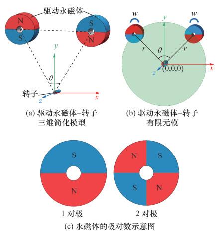
图 2a为驱动永磁体-转子三维简化模型。利用Maxwell模块建立圆周分布驱动永磁体-转子有限元模型, 如图 2b所示。驱动永磁体与转子的两端面均在同一平面上, 且长度均为40 mm, 以转子轴线为z轴, 转子其中一端面中心为原点, 并以该端面为x-y平面, 建立Descartes坐标系, 以z点坐标为0的x-y平面为基准, 在该平面上, 2个驱动永磁体圆心与转子圆心夹角为θ, 仿真过程采用参数化建模以便于后期修改模型, 驱动永磁体与转子充磁方式均为径向充磁。图 2c为永磁体的极对数示意图, 其中永磁体磁极数为永磁体的极对数的2倍。
图 2 驱动永磁体-转子仿真三维简化模型
由于生长棒转子与驱动永磁体之间为人体软组织结构, 而人体软组织的磁导率可近似为真空或空气的磁导率, 因此将有限元分析的求解域中的材料设置为真空。驱动永磁体及转子规格参数见表 1, 经换算后可得出转子转动惯量为1.769×10⁻⁸ kg·m2。永磁体材料为钕铁硼, 属性参数见表 2。有限元模型仿真参数符号及定义见表 3
表 1 驱动永磁体及转子规格参数表
参数 驱动永磁体 转子
内径/mm 11 2
外径/mm 50 5
厚度/mm 40 40
表 2 钕铁硼(NdFe35)材料属性参数
参数 数值
磁场强度/(A·m-1) 890 000
相对磁导率 1.100
电导率/(S·m-1) 6.250×10⁵
剩磁/T 1.33
矫顽力/(kA·m-1) 860
最大磁能积/(kJ·m-3) 342
牌号 S-NdFeB-360/96
密度/(kg·m-3) 7 500
表 3 有限元模型仿真参数及定义
参数 定义
w/(r·min-1) 驱动永磁体同步旋转角速度
q/mm 转子外径
a/mm 驱动永磁体外径
θ/(°) 驱动永磁体与转子间夹角
s 驱动永磁体及转子极对数
x/mm 转子端面某点的x轴坐标
y/mm 转子端面某点的y轴坐标
r/mm x-y平面上, 驱动永磁体中心与转子中心的距离

3 仿真结果及参数优化分析

在Maxwell模块中建立好参数化模型后进行三维仿真分析, 其中边界为Vector Potential, 网格划分方法采用自适应网格, 后续仿真结果以三维模型剖面进行展示, 所有的仿真分析设置驱动永磁体、转子长度均为40 mm。通过参数化扫描的方法在给定值域内分别对wqθs、(x, y)进行参数化仿真, 比较不同条件下转子最大扭矩的变化情况并确定优化后转子可连续转动区域, 综合得出驱动永磁体驱动转子的设计方案。

3.1 转子最大扭矩

q =5 mm、a =50 mm、θ =60°、s =1、r =120 mm的驱动永磁体圆周排布模型为例, 转子位置不变且不转动, 驱动永磁体绕各自中心轴以w =50 r/min的速度同步旋转, 通过计算获得驱动永磁体从初始静止位置分别转过90°、180°和270°时的磁力线分布如图 3a所示, 磁场强度如图 3b所示; 保持2个驱动永磁体同步转动, 转子不转, 得到的正弦曲线的峰值即为最大扭矩, 转子扭矩随时间变化的曲线如图 3c所示; 其他参数不变, 使转子保持转动, 得到转子旋转角度随时间变化的曲线如图 3c所示。研究发现, 转子的最大扭矩为32.847 N·mm, 且转子能在上述条件下随驱动永磁体正常转动。
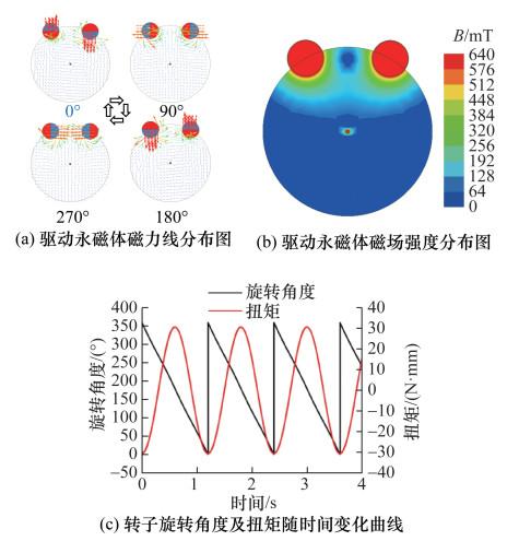
图 3 驱动永磁体-转子模型仿真结果
分析θsqw对转子最大扭矩的影响规律。在其他基本参数不变的条件下, 保证转子磁极对数与驱动永磁体的一致, 转子位置不变, 考虑到θ过小时会造成模型干涉, 这里设定θ变化范围为40°~180°, 设定增量为20°进行参数化扫描; s取值为1、2、3; q的变化范围为4~8 mm, 设定增量为1 mm; 由于生长棒的延长速率不宜过大, 这里设定w变化范围为20 ~100 r/min, 设定增量为10 r/min进行参数化扫描, 得到各参数对转子最大扭矩影响的仿真结果, 如图 4所示。
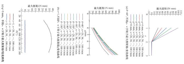
图 4 θsqw对转子最大扭矩的影响
研究发现, 转子最大扭矩随着θ变化存在一个极值, 当θ =120°时, 转子最大扭矩最大, 使转子最大扭矩由大到小变化的θ依次为120°、140°、100°、160°、80°、180°、60°、40°。s越大, 转子最大扭矩急剧下降; q越大, 转子最大扭矩越大; w对转子最大扭矩无影响。

3.2 转子连续转动域
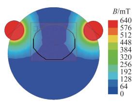
转子可连续转动的分布空间对临床治疗有较大影响, 本节研究优化后转子的连续转动域。由于生长棒需植入在人体脊柱两侧, 其中一端在T6和T8椎体处固定, 另一端在L4和L5椎体处固定[3], 因此设定转子端面某点坐标(x, y, 0)中x为-60~60 mm, y为-20~80 mm。以矩形框来表示转子坐标变化范围, Ⅰ区域为转子可连续转动区域, 在该区域内, 转子能够随驱动永磁体同步转动; Ⅱ区域为转子不可连续转动区域, 在此区域中, 转子无法实现随驱动永磁体同步转动, 得到优化后转子连续转动域的仿真结果, 如图 5所示。研究发现, 优化后转子有较大的连续转动域。
图 5 优化后转子连续转动域

3.3 优化分析

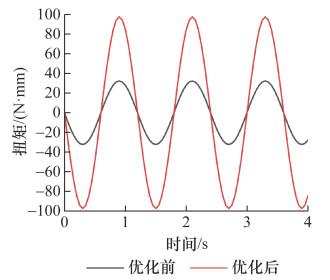
将优化后的参数进行仿真验证, θ为120°、s为1、q为8 mm、w为50 r/min, 且保证转子磁极对数与驱动永磁体一致, 得到优化前后转子扭矩随时间变化曲线如图 6所示。结果表明, 优化前转子最大扭矩为32.847 N·mm; 优化后转子最大扭矩为98.970 N·mm, 比优化前提升了201%, 且转子能够连续转动的分布空间更大。
图 6 优化前后转子扭矩随时间变化曲线

4 磁控驱动器实验验证

为验证上述仿真结果, 搭建转子扭矩测量装置(见图 7)。该装置电机连接联轴器, 联轴器另一端和转轴连接, 驱动永磁体和齿轮通过螺栓固定连接。电机带动中间齿轮转动, 中间齿轮带动两边齿轮转动, 从而实现驱动永磁体同步转动。扭矩传感器通过顶丝、固定块、联轴器等进行固定, 转子、螺杆与夹头通过联轴器固定在扭矩传感器上。将上述优化前后仿真结果进行实验验证, 并进行了7组重复性验证, 得到优化前后转子最大扭矩均值分别为30和90 N·mm, 相对误差分别为8.7%和9.06%, 永磁体均可稳定旋转。
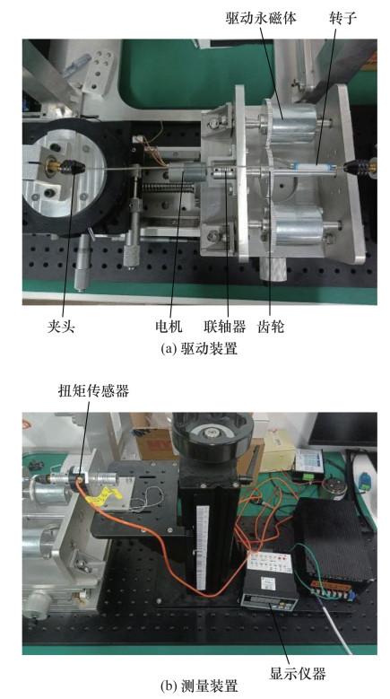
图 7 转子扭矩测量装置
为检验磁控驱动器的性能, 搭建图 8a的实验装置, 其中椎弓根螺钉用于固定生长棒, 生长棒的两端放置在椎弓根螺钉的小孔内, 通过旋转螺母固定生长棒。生长棒由永磁转子、减速器、丝杠和牵伸杆件等串联而成, 当外部驱动器产生旋转磁场使得生长棒内部转子发生转动时, 其输出扭矩作为减速器的输入, 经由减速器增益后的扭矩传递至丝杠, 再由丝杠实现旋转运动到直线运动的转换。将脊柱模型固定在磁控驱动器上, 并在脊柱两端固定椎弓根螺钉, 生长棒两端固定在椎弓根螺钉上。电机带动驱动永磁体旋转, 从而使生长棒内部转子转动产生转矩输入, 经扭矩增益及运动变换后生长棒可实现轴向延长。为测试生长棒的最大牵伸力, 搭建图 8b的实验装置, 装卡块用于固定生长棒, 将生长棒的延长端放置在传感器定位块上, 通过弹簧的压缩量确定生长棒的牵伸力, 并通过显示仪器显示出牵伸力值。实验结果表明, 生长棒最大牵伸力可达到413 N, 比MAGEC系统生长棒的最大牵伸力208 N[7]提高了近1倍。
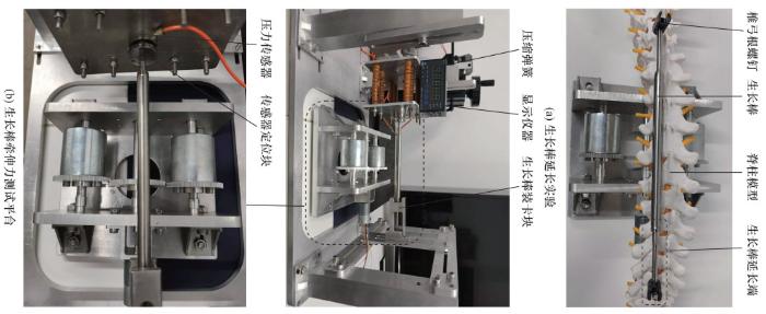
图 8 生长棒实验装置

5 结论

本文研究了驱动永磁体与转子间夹角、极对数、转子外径、驱动永磁体转速对转子最大扭矩的影响, 并确定了优化后转子能够连续转动的分布空间。研究发现: 永磁体极对数越多, 转子最大扭矩越小; 转子外径越大, 其最大扭矩越大; 转速对转子最大扭矩无影响; 驱动永磁体与转子之间夹角取120°时, 转子最大扭矩最大。优化后转子有较大的连续转动域, 且优化后的结果提高了转子最大扭矩及生长棒牵伸力, 生长棒牵伸力比MAGEC系统的提高了近1倍。
1
何沛檐, 裴葆青, 王唯, 等. 生长棒不同固定术式治疗早发性脊柱侧凸的生物力学分析[J]. 医用生物力学, 2021, 36 (6): 849- 854.

HE P Y , PEI B Q , WANG W , et al. Biomechanical analysis of different methods of growing rod fixation for early onset scoliosis[J]. Journal of Medical Biomechanics, 2021, 36 (6): 849- 854.

2
刘杨, 王伟君, 陆昕海, 等. 不同侧弯类型对青少年脊柱生理曲度及骨盆运动学特征影响[J]. 医用生物力学, 2023, 38 (6): 1160- 1166.

LIU Y , WANG W J , LU X H , et al. Effects of different scoliosis curves on physiological curvature of spine and kinematic characteristics of pelvis in adolescents[J]. Journal of Medical Biomechanics, 2023, 38 (6): 1160- 1166.

3
AKBARNIA B A , PAWELEK J B , CHEUNG K M C , et al. Traditional growing rods versus magnetically controlled growing rods for the surgical treatment of early-onset scoliosis: a case-matched 2-year study[J]. Spine Deformity, 2014, 2 (6): 493- 497.

DOI

4
CHARROIN C , ABELIN-GENEVOIS K , CUNIN V , et al. Direct costs associated with the management of progressive early onset scoliosis: Estimations based on gold standard technique or with magnetically controlled growing rods[J]. Orthopaedics & Traumatology: Surgery & Research, 2014, 100 (5): 469- 474.

5
CHEUNG J P Y , CAHILL P , YASZAY B , et al. Update on the magnetically controlled growing rod: Tips and pitfalls[J]. Journal of Orthopaedic Surgery, 2015, 23 (3): 383- 390.

DOI

6
AKBARNIA BA , MUNDIS JR GM , SALARI P , et al. Innovation in growing rod technique: A study of safety and efficacy of a magnetically controlled growing rod in a porcine model[J]. Spine, 2012, 37 (13): 1109- 1114.

DOI

7
CHEUNG J P Y , CHEUNG K M C . Current status of the magnetically controlled growing rod in treatment of early-onset scoliosis: What we know after a decade of experience[J]. Journal of Orthopaedic Surgery, 2019, 27 (3): 2309499019886945.

DOI

8
SUN X D , SHI Z , LEI G , et al. Analysis and design optimization of a permanent magnet synchronous motor for a campus patrol electric vehicle[J]. IEEE Transactions on Vehicular Technology, 2019, 68 (11): 10535- 10544.

DOI

9
ZHOU X , ZHU X Y , WU W Y , et al. Multi-objective optimization design of variable-saliency-ratio PM motor considering driving cycles[J]. IEEE Transactions on Industrial Electronics, 2021, 68 (8): 6516- 6526.

DOI

10
SHI Z , SUN X D , CAI Y F , et al. Torque analysis and dynamic performance improvement of a PMSM for EVs by skew angle optimization[J]. IEEE Transactions on Applied Superconductivity, 2019, 29 (2): 0600305.

11
BINGI K, PRUSTY B R, KUMRA A, et al. Torque and temperature prediction for permanent magnet synchronous motor using neural networks[C]// Proceedings of 2020 3rd International Conference on Energy, Power and Environment: Towards Clean Energy Technologies. Shillong, India: IEEE, 2021: 1-6.

12
GÜEMES J A , IRAOLAGOITIA A M , DEL HOYO J I , et al. Torque analysis in permanent-magnet synchronous motors: A comparative study[J]. IEEE Transactions on energy conversion, 2011, 26 (1): 55- 63.

DOI

13
王洪涛. 永磁体结构对永磁同步电机电磁特性的影响[J]. 组合机床与自动化加工技术, 2018 (4): 19-22, 28.

WANG H T . Influence of permanent magnet structure on the electromagnetic characteristics of permanent magnet synchronous motor[J]. Modular Machine Tool & Automatic Manufacturing Technique, 2018 (4): 19-22, 28.

14
EBRAHIMI H , TORKAMAN H , JAVADI H . Simultaneous improvement of cogging torque and torque density in axial flux-switching permanent magnet motor[J]. IET Electric Power Applications, 2024, 18 (3): 312- 324.

DOI

15
YAN D , YAN Y , CHENG Y Q , et al. Research on cogging torque reduction method for permanent magnet synchronous motor accounting for the magnetic pole edge effect[J]. IET Electric Power Applications, 2024, 18 (1): 64- 75.

DOI

16
于仲安, 沈林辉, 梁建伟, 等. 六相永磁同步电机转矩波动抑制研究[J]. 组合机床与自动化加工技术, 2022 (4): 118- 122.

YU Z A , SHEN L H , LIANG J W , et al. Research on torque ripple suppression of six-phase permanent magnet synchronous motor[J]. Modular Machine Tool & Automatic Manufacturing Technique, 2022 (4): 118- 122.

17
周大伟, 陆丽, 杨长青, 等. 基于遗传算法的高速永磁电机联合仿真优化[J]. 组合机床与自动化加工技术, 2023 (11): 69- 73.

ZHOU D W , LU L , YANG C Q , et al. Co-simulation optimization of high speed permanent magnet synchronous motor based on genetic algorithm and TOPSIS method[J]. Modular Machine Tool & Automatic Manufacturing Technique, 2023 (11): 69- 73.

18
卢东斌, 欧阳明高, 谷靖, 等. 四轮驱动电动汽车永磁无刷轮毂电机转矩分配[J]. 清华大学学报(自然科学版), 2012, 52 (4): 451- 456.

DOI

LU D B , OU YANG M G , GU J , et al. Torque distribution algorithm for a permanent brushless DC hub motor for four-wheel drive electric vehicles[J]. Journal of Tsinghua University (Science and Technology), 2012, 52 (4): 451- 456.

DOI

19
张猛, 肖曦, 李永东. 基于区域电压矢量表的永磁同步电机直接转矩预测控制[J]. 清华大学学报(自然科学版), 2008, 48 (1): 1- 4.

DOI

ZHANG M , XIAO X , LI Y D . Predictive direct torque control of PM synchronous motors based on an area voltage vector table[J]. Journal of Tsinghua University (Science and Technology), 2008, 48 (1): 1- 4.

DOI

Outlines

/